 |
 |
![]()
![]()
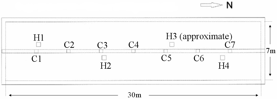
Figure 2a: Scheme of Crematorium II gas chamber from above. C1-C7 mark support pillars, H1-H4 Zyklon holes. Because roof shifted when dynamited, relative distances (e.g., between C1 and H1) differ today (see Figure 10 and relevant discussion).
![]()
![]()
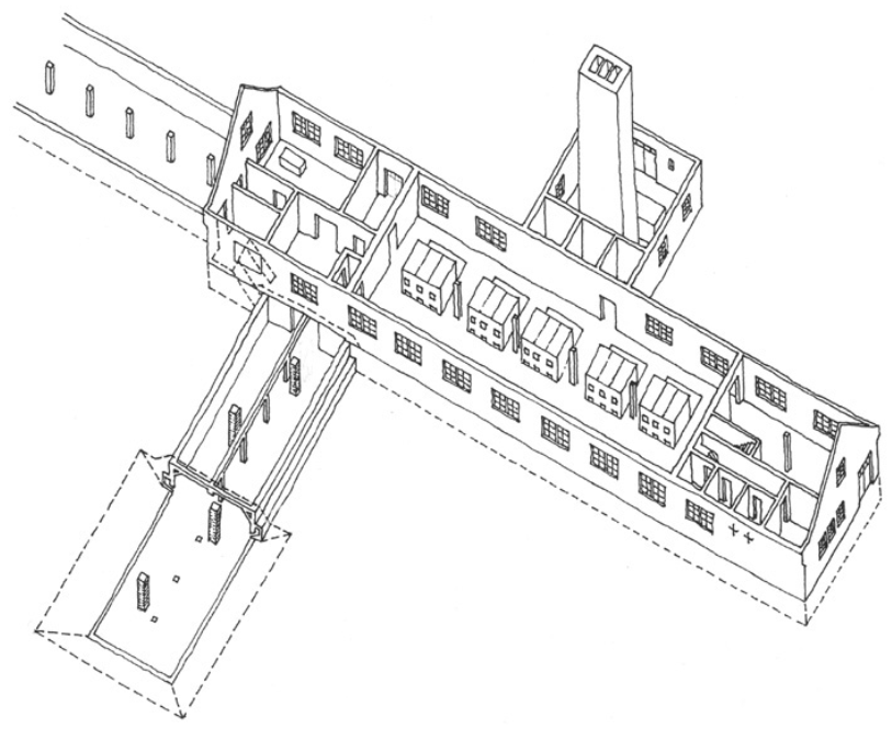
Figure 2b: Schematic drawing of entire crematorium; dotted lines around gas chamber show embankment. Thanks to Marc Downing. An earlier version of 2b appeared in Robert Jan van Pelt, The Case for Auschwitz (Bloomington: Indiana University Press, 2002), p. 190.
© Holocaust and Genocide Studies, Oxford University Press, Volume 18, Number 1, Spring 2004, pages 68-103. Used with permission.

