|
|
 |
 |
AUSCHWITZ:
Technique
and Operation
of
the Gas Chambers © | |
|
| |
 |
Back |
 |
Contents |
Page 340 |
 |
Home
Page |
Forward |
 |
| |
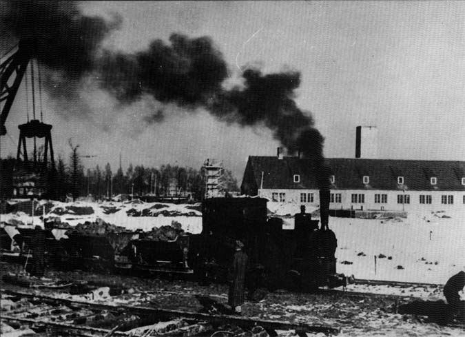
| Photo 17 |
 |
|
| Photo 17a |
 |
|
Photo 17 and 17a:
[PMO neg.
no. 20995/494, Kamann series. This photo is also in the Archives of
the Warsaw Central Commission for research into Hitlerian crimes in
Poland, but as it was never identified or communicated to the
Auschwitz Museum, it remained unexploited until it was rediscovered
in the Bauleitung Album.] |
| |
South/north view of the greater part of the south side
of Krematorium II and its Leichenkeller 1 (gas chamber), not yet
covered with earth, taken on the same day as Photo 15 and 16,
probably between 9th and 11th February 1943.
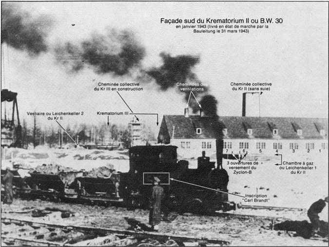
Photo
17a, with the explanatory inscriptions by the author, is taken
from the "Auschwitz Album" (Editions de Seuil, page
211). This photo provides the following information: |
| |
|
| · |
The height of the ventilation
chimneys of Krematorium II has been increased above that of Photo
13; |
| · |
The furnaces had not yet been
working at full capacity because there are no soot stains on the
collective chimney. |
| · |
Leichenkeller 1 has only 3 of
the 4 openings for pouring Zyklon-B with which it was finally
fitted. Rising about 55 or 60 cm above the roof, they were later
covered to a depth of about 45 cm with gravel and earth, so that
only 10 to 15 cm remained visible. This would explain why they did
not stand out much when the grass grew and why they are so
indistinct on the next Photo, though this seems to be in
contradiction with aerial photos taken by the Americans in 1944
which shows them to be higher.
[The latest interpretation of
these openings by Robert Faurisson should be mentioned: they are
simply ventilation chimneys. In that case what was wrong with the
ventilation and air extraction system installed in Leichenkeller 1?
What is more, he does not take into account that the SS designated
them in writing as "wire mesh introduction devices" closed by
“wooden lids”. What ventilation can there be if they are closed by
lids?]
|
| · |
In the foreground is a
narrow-gauge locomotive belonging to Messrs Carl Brandt of
Magdeburg, for which an order for the repair of a condensation valve
has been found in the correspondence concerning the construction of
Krematorien II and III. This firm worked at Birkenau on the drainage
and sewerage ditches and the laying of narrow-gauge railways to
facilitate the transport of the materials required for enlarging the
camp (for example, work on B.A.III, according to Brandt drawing 6158
of 15.3.43). |
|
Photo 17a:
Translation of
inscriptions: |
| |
| · |
Façade sud du Krematorium II ou
BW 30 / South side of Kr II or BW 30 |
|
| · |
En janvier 1943 (livré en état
de marche par la Bauleitung le 31 mars 1943 / in January 1943
(handed over in working order by the Bauleitung on 31st March
1943) |
|
| · |
Vestiaire ou Leichenkeller 2 du
Kr II / Undressing room or Leichenkeller 2 of Kr II |
|
| · |
Cheminée collective du Kr III en
construction / Collective chimney of Kr III under
construction |
|
| · |
Krematorium III |
|
| · |
Cheminées des ventilations /
Ventilation chimneys |
|
| · |
Cheminée collective du Kr
III(sans suie) / Collective chimney of Kr II (with no soot
stains) |
|
| · |
3 ouvertures de versement du
Zyklon-B / 3 openings for pouring Zyklon-B |
|
| · |
Chambre à gaz ou Leichenkeller 1
du Kr II / Gas chamber or Leichenkeller 1 of Kr II |
|
| · |
Inscription “Carl Brandt”
|
| |
| |
AUSCHWITZ:
Technique
and operation
of the gas chambers
Jean-Claude Pressac
© 1989, The
Beate Klarsfeld Foundation |
 |
Back |
Page 340 |
Forward |
 |
|

