Documents 40 and 41
[PMO neg. nos 21334/121
(above) and 21334/120 (below)]
“Coffin [in fact corpse]
charging trolley” found in storage at the liberation of the camp.
While photographs were being taken, a former prisoner lay on the
charging slide in front of a cremation muffle to show how it was
used. It is difficult to imagine that such a trolley would enable 5
to 7 corpses at a time to be charged the muffle of a Topf furnace as
testified by certain Sonderkommando members after the war (one went
so far as to say 12). The maximum capacity were more like 3 corpses,
not “in good health” but reduced to “mussulman”
condition. |
| |
Document 42:
(Photo by the author)
In the ruins of Krematorium II furnace room, view
of the three sets of rails, set in the floor in front of furnace 1,
on which the corpse charging trolley was to run. Though redundant
after the charging method was changed, these rails were not removed.
|
| |
Document 43
[Sketch by David Olère]
View of the furnace room of Krematorium III, looking east
west, drawn by David Olère after his return from deportation. The
sketch shows the simplified charging method, using the “corpse
stretcher”. The absence of the rails in front of the furnaces in
Olère's memory is significant; since they served no purpose, his
visual memory did not retain them. The shallow trough of water,
along which the victims’ corpses were dragged from the lift at the
end of the room, is on the right. |
| |
Document 44
(Photo by the author)
Entrance to the Leichenkeller 1 (gas chamber) sewer manhole,
situated on the outside, against the center of the western wall. The
top of the metal ladder can be seen. |
| |
Document 45
(Photo by the author)
View
of the inside of the manhole of document 46 with its access ladder.
On the left is the rod running from the waste water stop cock to its
control wheel above ground. The location can be seen on Bauleitung
drawing 1300 of 18/6/42. |
| |
Document 46
(Photo by the author)
Concrete cover with metal handle, weighing about 20 kg,
originally made for the manhole of document 44 and 45, now next to
the remains of an opening on the roof of Leichenkeller 1 (the gas
chamber) of Krematorium II, through which Zyklon B was
poured. |
| |
Document 47
(Photo by the author)
General view, looking roughly south north, of the ruins of
the Krematorium III gas chamber, very overgrown with vegetation. In
the center the four supporting pillars are still upright. The top of
the sewer manhole is on the left, against the west wall, raised
considerably above the ground. |
| |
Document 48
(Photo by the author)
Close up view of the manhole of document 47, made up of 4 to
6 sections of concrete pipe and with a concrete lid in two pieces
(only one of which remains). This type of manhole has no built in
access ladder. In the background is one of the pillars that
supported the roof of the Krematorium III gas chamber. |
|
| |
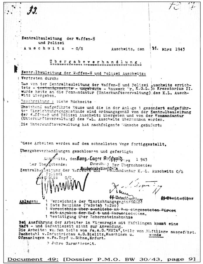
| Document 49 |
 |