|
|
 |
 |
AUSCHWITZ:
Technique
and Operation
of
the Gas Chambers © | |
|
| |
 |
Back |
 |
Contents |
Page 465 |
|
Home
Page |
Forward |
 |
| |
 |
Document 9 |
|
|
Document 9:
[PMO photo neg. no. 293] |
|
| |
|
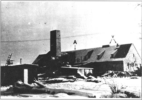
| The north side and west end
of Krematorium II nearing completion in December 1942 or January
1943. The Krematorium proper, containing principally the five
3-muffle furnaces, is located in A. At the end of the Krematorium
and extending the building line to the west is one end of
Leichenkeller 2, the future underground undressing room, indicated
as B’. The small hut B in the center of the picture was to be
replaced by one of the stable type, running north-south, to be used
as a temporary undressing room. At the southern exit of the hut is
the Krematorium basement access stairway E, leading to the gas
chamber, overlooked by the two north side windows on the right.
Above, on the roof, are the Krematorium ventilation outlets and
fresh air intake V. whose chimneys were later to be raised higher.
This photo shows that anyone never having seen a plan of the
building and not knowing of the underground flues leading from the
furnaces to the collective chimney, would logically tend to assume
that the fumaces were arranged around the chimney. |
|
|
| |
| |
| Document 10 |
 |
| |
|
| |
Document
10: |
| |
|
| |
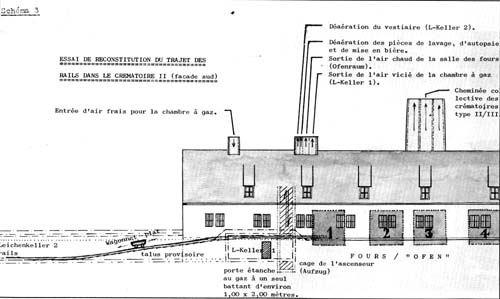
RECONSTITUTION OF
THE ROUTE OF THE RAILS IN
KREMATORIUM II (south side)
|
| |
|
| |
KEY:
|
| |
|
| |
· |
Entree d'air frais pour la
chambre à gaz /
Fresh air intake for gas chamber |
| |
· |
Désaération du vestiaire /
Undressing room (Leichenkeller 2) air outlet |
| |
· |
Désaération des pièces de
lavage, d’autopsie et de mise en bière /
Washing, dissection and
laying out rooms air outlet |
| |
· |
Sortie de l'air chaud de la
salle des fours /
Furnace room (Ofenraum) hot air outlet
|
| |
· |
Sortie de l'air vicié de la
chambre à gaz /
Gas chamber (Leichenkeller 1) noxious air outlet
|
| |
· |
Cheminée collective des
crématoires de type II-III /
Collective chimney of Krematorien
of type II/III |
| |
· |
Wagonnet plat / Flat
wagon |
| |
· |
Talus provisoire / Temporary
earth bank |
| |
· |
Porte étanche au gaz à un seul
bavant /
Single gas-tight door approximately 1 meter by 2
|
| |
· |
Cage de l'ascenseur / Lift shaft
|
| |
· |
FOURS / FURNACES (“OFEN”)
|
|
| To understand how the rails seem to pass through the
west wall, reference must be made to the building technique employed
for type II/IIII Krematorien, as it can be observed on a series of
Bauleitung photographs showing the construction of Krematorium III.
The longitudinal walls were built first, with recesses where the
ends of the transverse walls would subsequently fit. Thus the main
construction may appear from certain angles to be almost complete,
whereas in fact all the transverse walls are still to be built. The
provisional earth bank on which the narrow gauge rails were laid
made it easier to transport building materials between the surface
and basement levels. However, this arrangement prevented any passage
between the furnace room and the gas chamber, because the entrance
to the latter was beneath the rails and the bank. As this
arrangement is confirmed by contemporary photographs, it is obvious
that members of the Sonderkommando would not have been able to bring
corpses from the gas chamber to the furnace room on flat wagons,
since the rails started in the future undressing room (Leichenkeller
2) and as long as they remained in place the gas chamber
(Leichenkeller 1) could not function because its entrance was
blocked. | |
| |
AUSCHWITZ:
Technique
and operation
of the gas chambers
Jean-Claude Pressac
© 1989, The
Beate Klarsfeld Foundation |
|
Back |
Page 465 |
Forward |
|
|