|
|
 |
 |
AUSCHWITZ:
Technique
and Operation
of
the Gas Chambers © | |
|
| |
 |
Back |
 |
Contents |
Page 484 |
 |
Home
Page |
Forward |
 |
| |
| middle of its length [1/1 to 1/7]. On either side of these
pillars there were four others [C I to C4], two on each side. [Here
Tauber is mistaken. This arrangement is found only in the gas
chamber of Krematorium III. In Kr II, they were in a row down the
east side of the room]. The sides of these pillars, which went up
through the roof, were of heavy wire mesh. Inside this grid. there
was another of finer mesh and inside that a third of very fine mesh.
Inside this last mesh cage there was a removable can that was pulled
out with a wire to recover the [inert] pellets from which the gas
had evaporated. |
| |
[see Document 14, based on Michal Kula's
description of the Zyklon-B (hydrocyanic acid fixed on small
pellets of silicon) introduction columns. Tauber made a very
slight mistake in saying that there was a third FIXED cage in the
column.] |
| |
| Besides that, in the gas chamber there were electric wires
running along the two sides of the main beam supported by the
central concrete pillars [to supply 16 sealed lamps, observation
confirmed by a Bauleitung drawing]. The ventilation was installed in
the walls of the gas chamber. Communication between the room and the
ventilation installation proper was through small holes along the
top and bottom of the side walls. The lower openings were protected
by a kind of muzzle, the upper ones by whitewashed perforated metal
plates. |
| |
[See Documents 15, 16 and 17. Some of these
upper ventilation hole covers from Leichenkeller 1 of Krematorium
II made of zinc sheet covered with a white layer, were submitted
to toxicological analysis in December 1945. After appropriate
chemical treatment, scrapings from this white layer gave Prussian
blue or ferric ferrocyanide, or ferric thiocyanate, dyes
indicating, specifically, but not very precisely, the presence of
hydrocyanic compounds.] |
| |
| The ventilation system of the gas chamber was coupled to the
ventilation ducts installed in the undressing room. This ventilation
system. which also served the dissection room [11]. was driven by
electric motors in the roof space of the crematorium
[12]. |
| |
[Tauber was the ONLY witness to formally indicate that
the undressing room and the dissecting room WERE ALSO VENTILATED.
Thirty-live years later, nobody had yet noticed! But in order to
know that the ventilation systems were separate, contrary to what
he thought, he would either have had to he present during their
installation or to have climbed on the roof and found the four
separate air extraction outlets inside a single chimney.]
|
| |
| The gas chamber had no water supply of its own. |
| |
[A Bauleitung inventory drawing indicates that three
taps were in fact installed IN the gas chamber. But they were
destroyed in the first gassings and it was decided not to replace
them.] |
| |
| The water tap was in the corridor and a rubber hose was run from
it to wash the floor of the gas chamber. At the end of 1943, the gas
chamber was divided in two by a brick wall to make it possible to
gas smaller transports. In the dividing wall there was a door
identical to that between the corridor and the original gas chamber.
Small transports were gassed in the chamber furthest from the
entrance from the corridor. |
| |
[One of the very few contestable points in the
deposition. It would seem more logical to gas in the gas chamber
CLOSEST to the entrance, as this meant less distance to transport
the corpses and the ventilation system at the far end of the gas
chamber must have been inefficient because it was poorly
designed.] |
| |
| The undressing room and the gas chamber were covered first with
a concrete slab [the ceiling] then with a layer of soil sown with
grass. There were four small chimneys, the openings through which
the gas was thrown in, that rose above the gas chamber. These
openings were closed by concrete covers with two
handles. |
| |
[An inventory in the Krematorium II handover document
indicates “4 Holzblenden / 4 wooden covers” (page 12 of PMO file
BW 30/43). Mistake on Tauber's part, or were the covers changed in
the light of experience?]. |
| |
| Over the undressing room, the ground was higher than the level
of the yard and perfectly flat. The ventilation ducts led to the
[air extraction] pipes and the chimneys located in the part of the
building above the corridor and undressing room [13, 13']. I
would point out that at first the undressing room had neither
benches nor clothes hooks and there were no showers in the gas
chamber. These fittings were not installed until autumn 1943 in
order to camouflage the undressing room and gas chamber as a bathing
and disinfestation facility. The showers [24 dummy wooden shower
heads] were fitted to small blocks of wood sealed into the [plain]
concrete roof of the gas chamber [see Documents 18 and 19].
There were no pipes connected to these showers, from which no water
ever flowed. |
| |
| As I have already said, there was a lift [9] in the corridor [3]
or rather a goods hoist [see Document 20. A temporary hoist
was installed pending delivery of the electric lift] to carry the
corpses to the ground floor. At this level [Document 21], on
emerging from the lift, there was a door [14a] leading to the
“boiler room”, [14] where the cremation furnaces [01 to 05] were,
and the other door [15a], on the opposite side led to a store room
were the corpses were put [temporarily]. In addition, there was a
vestibule [16] there, which was reached through an entrance [16a.
Document 22] facing the access door to the crematorium. From
this vestibule, one entered through the right hand door [l6b] into
the dissecting room [11]. Between this room and the corpse store,
there was a WC [17] reached through a door [11a] from the dissecting
room. The left hand door [16c, coming front the vestibule] led to
the “boiler room” on the firebox side of the cremation furnaces.
They were in a row, equally spaced. There were five furnaces, each
fired by two hearths [G1 and G2]. On the other side, where the exit
front the lift was [14a], were the muffles [M1 to M3] [or cremation
ovens], three per furnace. It was possible to put five human corpses
in each muffle, which was closed by an iron door bearing the
inscription “Topf”. Beneath each muffle, there was a space for a bin
to collect the ashes, also closed by an iron door made by the same
firm. Behind the furnaces, on the left, on the side of the access
door from the crematorium yard, was the coke store [18]. Going to
the end of the yard [slip of the tongue. Tauber means "at the end of
the furnace room"] was a narrow corridor [19] from which a door
[20a] led to a small room [120] reserved for the SS [see Document
23]. One of the windows [20b] of this room looked onto the
“boiler roorn” on the muffle side, and the second [20c] onto the
yard behind the crematorium. This room was next to that of the head
of the Kommando (Kommandoführer) [21], which had a window [21a]
looking out on the back yard. |
|
 |
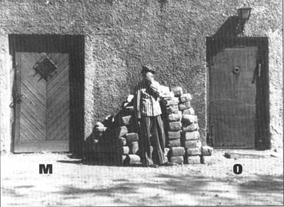
Document 7.
[Archives of the Central Commission for the investigation
of Hitlerite crimes in Poland, ref. 5150 B]
Northwest
side of Krematorium I, taken in 1945 during its reconstruction.
Above M, is the acess door to the former "boiler room". This door
was converted back intro a window as it was originally. Above O, is
the real entrance door to the crematorium, fitted with a gas-tight
door with a peep-hole. I do not know whether this is how it was
found when the camp was liberated. |
|
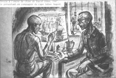
Document 8
Indian Ink sketch by David Olère, drawn in 1947, showing
himself in the company of the Capo Julius August Brück.
|
 | |
| |
AUSCHWITZ:
Technique
and operation
of the gas chambers
Jean-Claude Pressac
© 1989, The
Beate Klarsfeld Foundation |
 |
Back |
Page 484 |
Forward |
 |
|

